From Deep Learning to Classical Computer Vision: Developing an Industrial Quality Control System
Introduction
During my internship, I worked at Bartels Mikrotechnik GmbH in Dortmund, Germany, a company specializing in microtechnology, microfluidics and micropump solutions. My main project focused on developing an industrial computer vision system for automated quality control.
The Challenge
The existing quality inspection process relied on manual visual checks. The goal of my project was to develop a camera-based system that could automatically detect positional deviations of components and evaluate them using defined tolerance limits. This would make the inspection process more objective, reproducible and efficient.
Exploring Different Approaches
At the beginning, I worked with an AI-based approach using machine learning and deep learning methods for image recognition. Afterwards, I developed a rule-based computer vision approach as an alternative.
The AI-based approach showed potential, but it would have required a sufficiently large and well-prepared image dataset. This included sorting components, capturing many images and preparing the data for model training.
Why We Chose Classical Computer Vision
For the final solution, the company decided to continue with the rule-based approach because it offered greater transparency and easier maintenance. With this approach, it was possible to directly understand how features were detected, how measurements were calculated and why a component was classified in a certain way. This also made the system easier to adjust and maintain after the end of my internship.
Controlled Test Environment
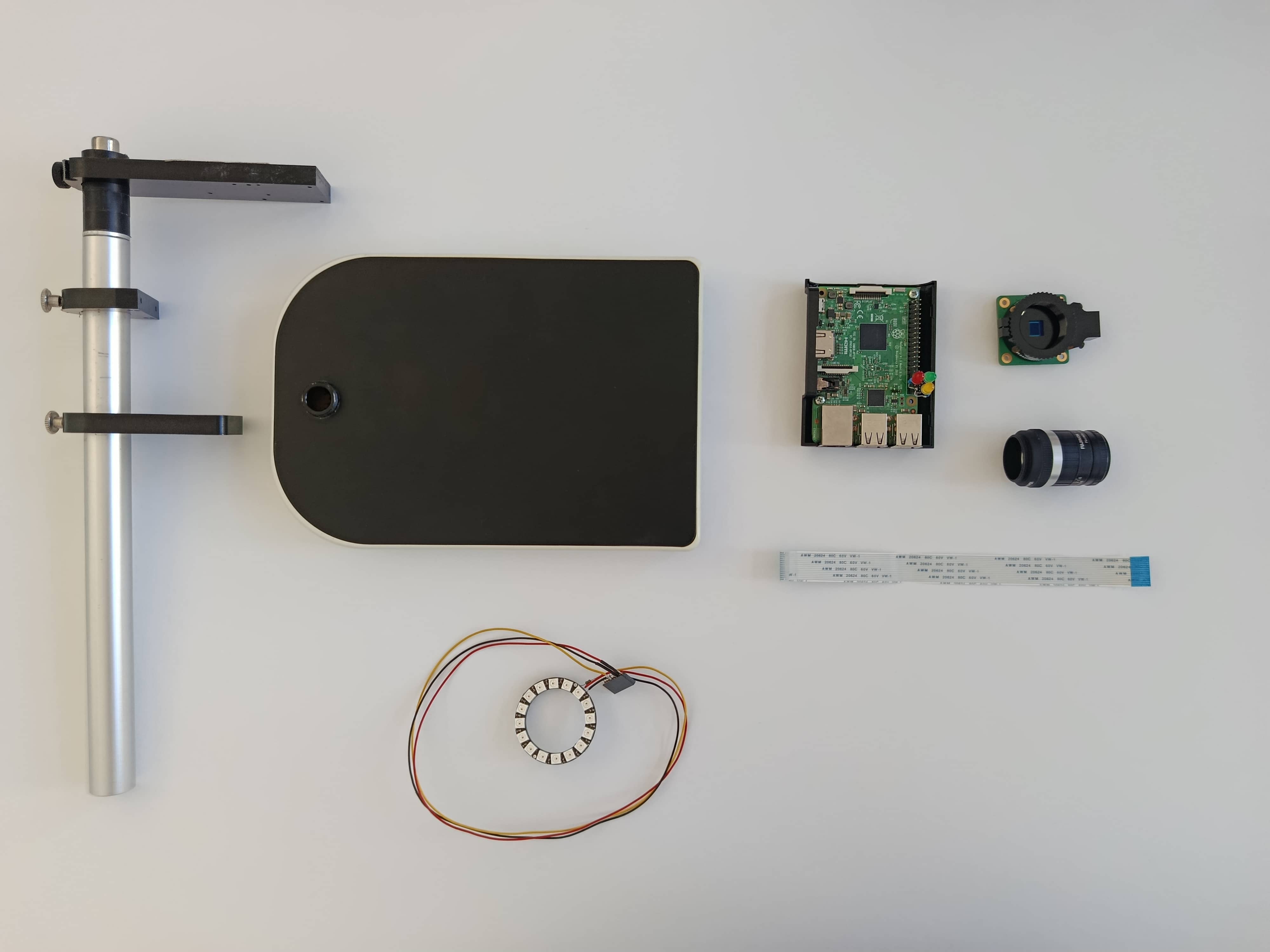
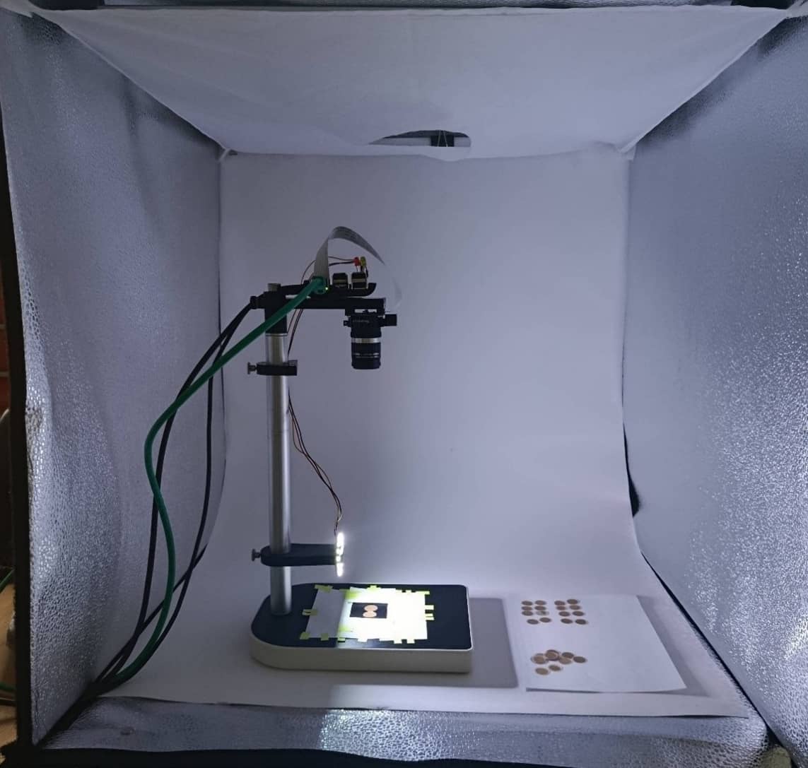
To ensure reproducible measurements, I developed a controlled test environment with a fixed camera position and consistent lighting conditions. The setup consisted of a Raspberry Pi, a camera with a fixed lens, an LED ring light, a microscope stand for stable positioning and a photo box to minimize interference from ambient light.
Actuator Module
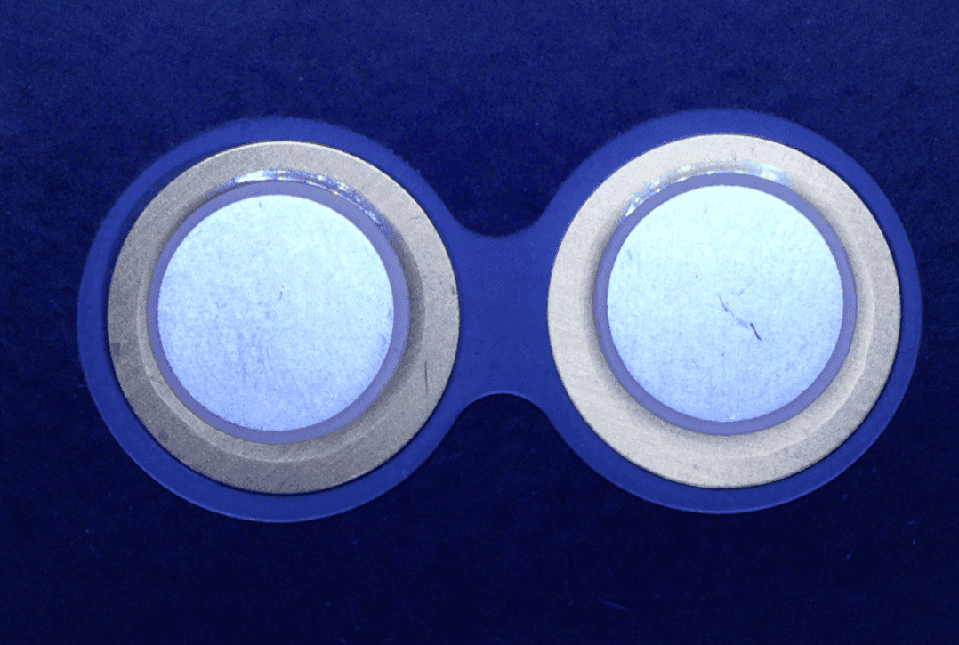
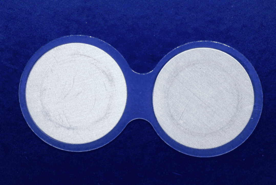
The actuator module is a central component of the micropump. With a length of 30 mm, the micropump is designed to transport very small quantities of liquids or gases in a precise and controlled manner. The actuator module converts electrical signals into mechanical motion and is essential to the pump's operation. These micropumps are used in fields such as biotechnology, medical technology, trace detection at airports and space applications.
Camera Calibration
A camera projects the three-dimensional world onto a two-dimensional image. During this process, optical distortions caused by the camera lens can occur. To correct these distortions, I performed camera calibration using a chessboard pattern. For this purpose, I prepared several small chessboard patterns for the calibration process.
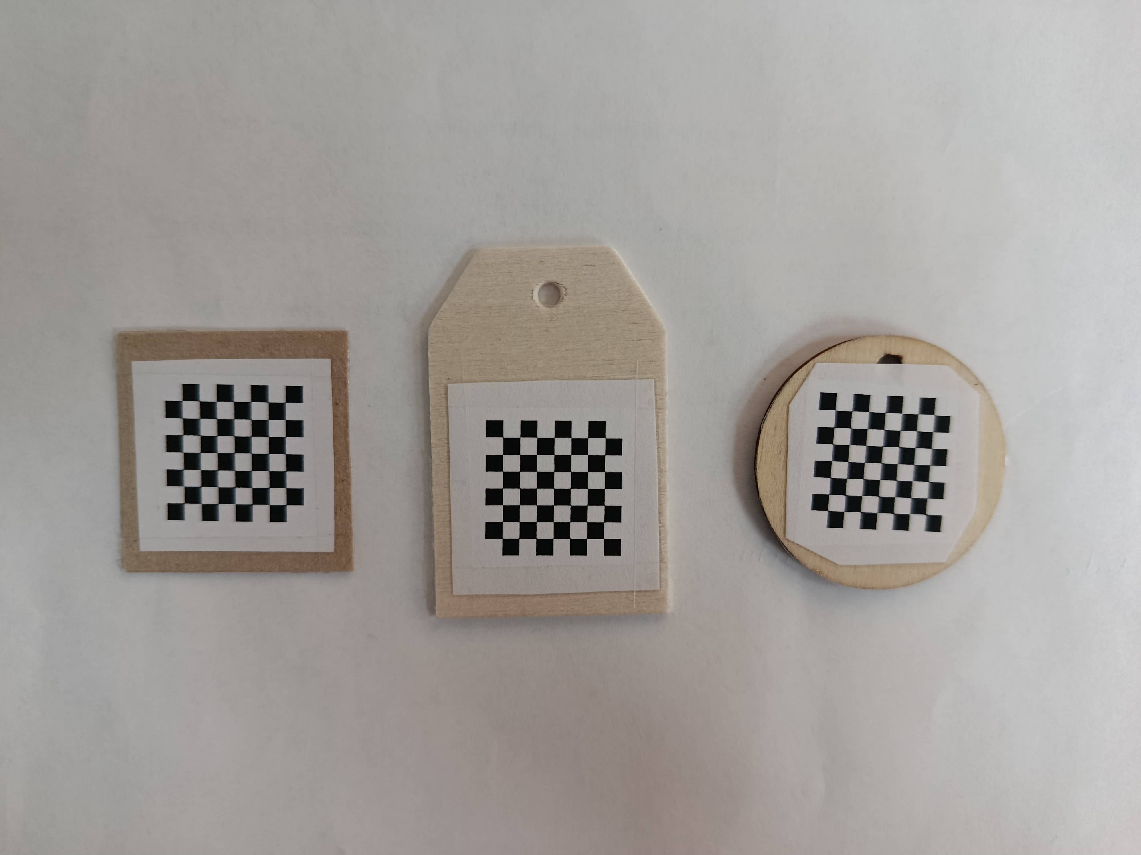
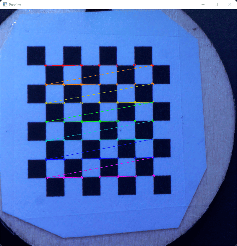
I chose this method because it is widely used, well-documented and directly supported by OpenCV. The library detects the inner corners of the chessboard in multiple images captured from different perspectives and uses their known real-world coordinates and corresponding image coordinates to estimate the intrinsic camera parameters and distortion coefficients.
These calibration parameters are then used to correct distortions in newly captured images, providing more accurate image data for subsequent measurement and analysis steps.
Interactive Configuration
To simplify the configuration of the circle detection, I developed an interactive configurator using OpenCV. Two control windows allow the detection parameters to be adjusted while a separate preview window displays the results in real time. Detected outer circles are highlighted in blue and inner circles in green, making it possible to immediately see how parameter changes affect the detection.
Measurement and Evaluation
After detecting the relevant geometric features, the system calculates the positional deviations of the components and converts the measurements into real-world units (from pixels into millimeters). The results are visualized directly on the captured image, including the detected circles, calculated distances and positional information.
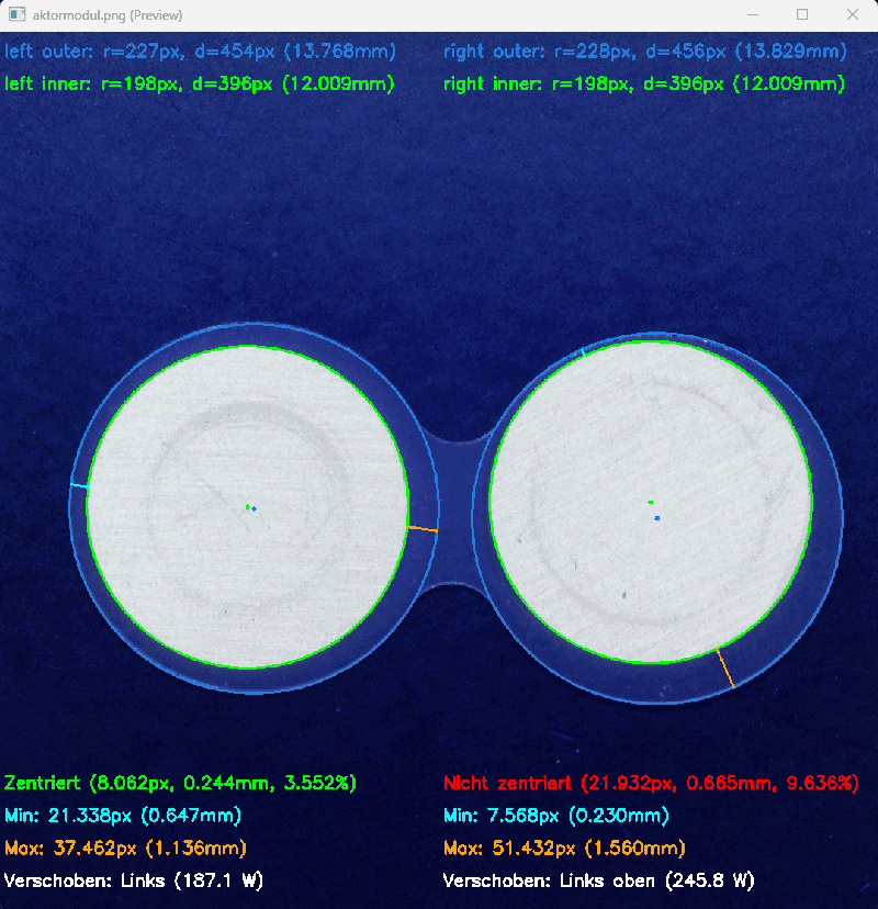
In this example, a tolerance limit of 0.5 mm defines how far each piezo module may deviate from its intended position on the transparent film. The system then automatically determines whether the actuator module meets the required specifications.
Conclusion
One of the most important lessons from this project was that choosing the right technology is not about using the most advanced approach but about finding the solution that best fits the technical and organizational requirements.